Matching Flange Standards to Electromagnetic Flow Transmitter to Avoid Delays
Sep. 22, 2025
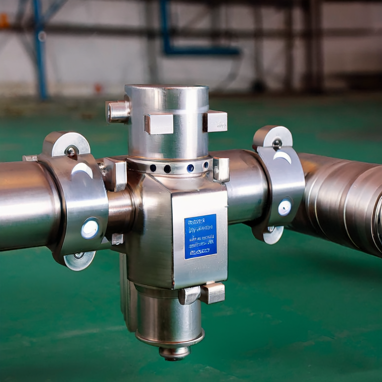
electromagnetic flow transmitters are crucial devices for measuring fluid flow, widely used in various industries, including water treatment, chemical processing, and oil & gas. Ensuring proper compatibility between these transmitters and flange standards is essential to avoid installation delays and operational inefficiencies. This article explores how to effectively match flange standards with electromagnetic flow transmitters, facilitating smooth installations and minimizing downtime.
Understanding Electromagnetic Flow Transmitters
- Definition and Function: Electromagnetic flow transmitters work on Faraday\'s Law of Electromagnetic Induction, measuring the voltage generated by the fluid as it flows through a magnetic field. They are used to accurately quantify the flow rate of conductive liquids.
- Applications: Commonly used in industries where fluid conductivity is essential, such as wastewater management, food processing, and chemical manufacturing.
The Importance of Flange Standards
- What are Flange Standards? Flange standards define the dimensions, materials, and tolerances for flanges used in piping systems. Different standards (ANSI, ISO, DIN, etc.) must be matched accurately to ensure system compatibility.
- Consequences of Mismatched Standards: Incorrect flange matching can lead to leaks, mechanical failure, and costly installation delays.
Step-by-Step Guide to Matching Flange Standards with Electromagnetic Flow Transmitters
- Step 1: Identify Your Electromagnetic Flow Transmitter Specifications
- Check the manufacturer\'s documentation for flange requirements, including size and type.
- Ensure that the transmitter is suited for the fluid type and flow conditions you will encounter.
- Step 2: Determine Applicable Flange Standards
- Identify the relevant flange standards based on regional and industry-specific requirements (ANSI, ISO, etc.).
- Consult authoritative sources like ASTM and ASME for specific guidelines on flanges.
- Step 3: Select the Right Flange Material
- Choose materials compatible with the fluid being measured to prevent corrosion.
- Consult the material compatibility charts provided by ASME or similar standards organizations.
- Step 4: Measure and Confirm Dimensions
- Carefully measure the dimensions of the electromagnetic flow transmitter and compare these with the selected flanges to assure proper fitting.
- Use a caliper for accuracy in measuring and a checklist for standard dimensions.
- Step 5: Pre-Installation Checks
- Verify the flange faces, ensuring they\'re clean and free from defects.
- Double-check all bolts and gaskets for compatibility and integrity before assembly.
- Step 6: Follow Installation Procedures
- Refer to the installation manual of the electromagnetic flow transmitter for specific torque requirements for bolts and types of gaskets to use.
- Implement phased tightening to ensure even pressure distribution across the flanges.
Utilizing Tools and Resources for Flange Standard Matching
- Consultation Services: Consider hiring professionals or consulting services with expertise in flow measurements for precise recommendations.
- Online Resources: Leverage websites such as gallopsensor for technical insights and resources regarding electromagnetic flow measurement and flange standards.
Key Considerations for Successful Measurement Compatibility
- Regular Maintenance: Once your system is installed, regular maintenance and inspection of flanges and transmitters ensure long-term reliability.
- Documentation: Maintain documentation of all specifications and measurements to facilitate future installations or repairs.
Final Thoughts on Flange Matching for Electromagnetic Flow Transmitters
- Effective matching of flange standards with electromagnetic flow transmitters protects against delays and enhances operational efficiency.
- Staying informed about industry standards and advancements can also help in making informed choices for the best materials and technology.
Latest News
Aug. 24, 2026
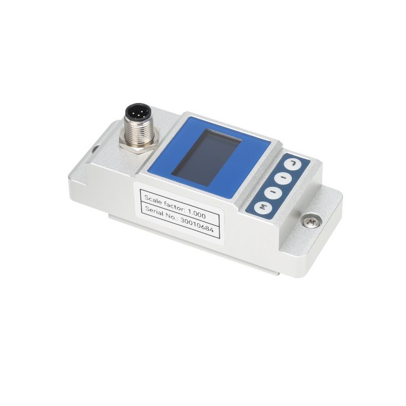
Water monitoring projects face unique challenges, particularly for industries reliant on precise flow measurement. In scenarios where traditional methods fall short—such as in fluctuating flow rates or environmental changes—the industrial radar open channel flow meter proves invaluable. Designed for reliable flow measurement even under adverse conditions, it addresses the pain points faced by
Aug. 24, 2026
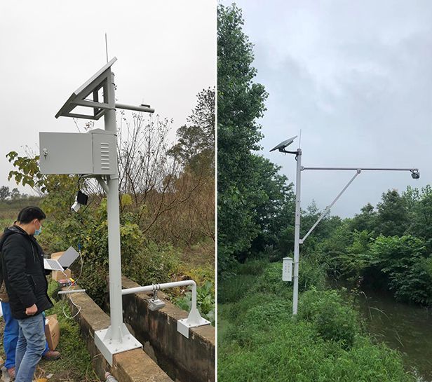
For professionals managing water resources—be it in municipal facilities, agriculture, or industrial applications—accurate measurement of flow rates in open channels is crucial. Traditional flow measurement techniques often lead to inaccurate readings due to environmental variables and equipment wear. Enter the radar open channel flow meter, a revolutionary tool designed for precision
Aug. 24, 2026
As industries strive for improved efficiency and data accuracy, the demand for advanced measurement technologies such as radar open channel flow meters has surged. Key sectors including wastewater treatment, irrigation management, and industrial processing face significant challenges with flow measurement inaccuracies, which can result in operational inefficiencies, increased costs, and
Aug. 24, 2026
The demand for precise flow measurement in open channels has grown significantly, driven by industries such as water management, wastewater treatment, and hydrology. This evolution has resulted in new challenges, including the need for enhanced accuracy, reliability, and ease of installation in flow measurement systems. Many industries struggle with outdated equipment that can't meet today's
